Tag Archive for: laser scan

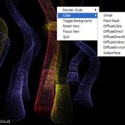
Exploring Point-Based Rendering in Pixar’s RenderMan [Point Clouds]

Creating animations of large point cloud datasets generated from terrestrial laser scanners and LiDAR has been an issue for a number of years. While it has been possible using tools such as Leica Geosystems Cyclone or Pointools, just to name a couple, it is still a very cumbersome task. It is exciting to see the CGI industry beginning to adopt the use of this data and developing applications that make it easier to visualize.

Over the last few years, a brand new technology has emerged for creating CGI effects that has already made a big impact on feature film production. It is called point-based rendering, and this powerful technique makes creating global illumination effects for feature film far more practical and efficient than before. In fact, this year the Academy of Motion Picture Art and Sciences awarded the creators of this innovation, Per Christensen, Michael Bunnell and Christophe Hery, with a Scientific and Engineering Academy award.

In this great article written by Nils O Sandys at CGSociety, we will look into the development of this important new technology, how point-based rendering works, and what this all means to the future of feature film production as we know it. Read the full article here.

Digitally Preserving American History

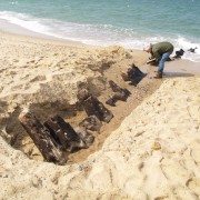
Erosion from recent storms uncovered the wreck by Harry R. Feldman Inc.

It is great to finally see people accepting the benefits of laser scanning as a means of digital preservation. Below is an excellent article posted by by Stefanie Geisler, Boston Globe Correspondent. Source

The wreck of the British warship that Paul Revere slipped by on his legendary journey to Lexington in 1775 has resurfaced in the shifting sands of Cape Cod, and federal park officials are seizing the moment by having the wreck “digitally preserved,” using three-dimensional imaging technology.

“We know the wreck is going to disappear again under the sand, and it may not resurface again in our lifetimes,” said William P. Burke, the historian at the Cape Cod National Seashore, noting that the last time any part of the HMS Somerset III had been sighted was 37 years ago.

“Somewhere down the road, if someone’s researching the Somerset, or the effects of ocean currents on shipwrecks, or anything like that, they will have this record,” he said. “We’re in the forever business. We’re looking at tomorrow, but we’re also looking ahead indefinitely.”

The Somerset fought in the American Revolution and had a crew of more than 400. In 1775, Paul Revere slipped through Boston Harbor past the ship before beginning his ride to warn the colonials the British were on the move. In his poem “Paul Revere’s Ride,” Henry Wadsworth Longfellow called it “a phantom ship, with each mast and spar/Across the moon like a prison bar.” The ship sank on Nov. 2, 1778 off the Cape.

After erosion from recent storms, about a dozen of the Somerset’s timbers were found poking through the wet sand at low tide in the national seashore in Provincetown. Park officials called on Harry R. Feldman Inc., a land surveying company from Boston, to make the three-dimensional rendering.

On Thursday, crews set up survey markers and a laser scanning instrument, said Michael Feldman, the company’s president.

The instrument was placed near the timbers, Feldman said. Using the scanner, the surveyors collect millions of data points that are used to create the three-dimensional rendering.

“The great thing about this technology is it not only shows a three-dimensional picture or video of what’s there, it also obtains data down to quarter-inch accuracy,” Feldman said.

It could take several visits to the site to complete the imaging. But when it’s done, the national seashore will have an animated fly-through of the wreck site — and anyone interested in seeing it won’t have to wait for the timbers to reappear.

The imaging will only capture the timbers that are showing. The rest of the wreck, which is buried in sand, might deteriorate if the site were excavated, Burke said.

Most of the crew survived when the ship sank, but they didn’t get a warm welcome when they reached the shore, he said.

“They were pretty upset with them, because the British had been blockading Provincetown for a long time during the war,” Burke said. “They marched all the survivors off the Cape, and eventually exchanged them for American prisoners.”

REVIEW:: ClearEdge3D EdgeWise™ – High Definition CAD Models Automatically From Point Clouds

EdgeWiseCompany: ClearEdge3D
Software:
EdgeWise™
Website: www.clearedge3d.com

Quick Pitch: Automatically extract vector planar surfaces from point cloud data.

Overview:
Having used just about every piece of software on the market related to processing and extracting vector information from point cloud data, I am always looking for the next best thing that will make my life and my team’s life easier. We have seen the hardware side of laser scanning come a long way in a very short period of time; however, the software side has not improved at the same blistering pace.

When the availability of ClearEdge3D’s EdgeWise™ software was announced here back in June and webinars were hosted to demonstrate the abilities of the software, I was anxious to get my hands on a copy of it to test it out for myself. While a little reluctant to offer demo licenses in the beginning, ClearEdge3D quickly began to realize that skeptics like myself were not willing to spend $5,000.00 on a piece of software that we have not had a chance to try out for ourselves, especially in this economy. They quickly began to recognize the needs of the market and responded accordingly by providing time-based pre-release beta trials to highly interested parties.

Installation:
The pre-release software I received (v. 1.0.2b) was easy to install, although there was an issue with the hardware lock driver on my Vista 64-bit laptop. This was quickly resolved by downloading the correct driver from the SafeNet website (Note: the updated drivers will be included on future distributions).

First Impression:
Right out of the box (figuratively speaking, as the software was downloaded from their website) I was very impressed with the overall look and feel of the software. ClearEdge3D was obviously interested in making their software easy to use and graphically pleasing-to-the-eye because they certainly did accomplish that. The UI is based on the latest Microsoft Office-type menu structure which made it very easy to jump right in.

EdgeWise-CaptureEase of Use:
ClearEdge3D insisted that I attend a 1-hour web-based training session and, while not necessarily needed due to the exceptional design and layout of the software itself, it did prove to be very beneficial and probably saved me the headache of learning by trial and error. With exception to a few terminology questions, I found the software’s left-to-right workflow very easy to use. Every step of the software’s conversion process was very well thought out and the routines made sense, technically speaking.

Technical Aspects:
While the software was primarily designed for the Architectural/BIM workflow, I have to admit that I was a little skeptical about the benefits of automatic conversion vs. the time needed to export the point cloud data to a format EdgeWise™ would accept (non-gridded PTX was the format of choice). Having been in the terrestrial laser scanning business over nine years, I know that point cloud data can be very cumbersome to deal with, especially when having to export to different formats. However, I was pleasantly surprised with EdgeWise’s ability to quickly import the various PTX files that I wanted to test.

NOTE: For those Cyclone users out there, EdgeWise™  is an automated “region grow patch, extend patch to all” batch routine. It really does a great job of quickly identifying planar surfaces and extending the edges to meet adjacent planes. The data import and processing time was a lot faster than I expected, but I did drastically reduce the number of points (to about 1 million).

Workflow:

  1. Export point cloud data (individual scans) to format accepted by EdgeWise™ (see FAQ on company’s website for more information on formats)
  2. Import individual scans into EdgeWise™
  3. Follow a few simple steps to identify the location of the scanner
  4. Extract ground surface (TIN)
  5. Let the software work its magic – it really is as simple as that!


Summary:
If you have a significant amount of basic models that need to be created from point cloud data, EdgeWise™ would likely be a good investment. Keep an eye on this product, because they are definitely on to something and, with a little direction from qualified users, they are on track to change our typical workflow.

Autodesk Announces Availability of Autodesk Navisworks 2010 with Point Cloud Operability

SAN RAFAEL, Calif., June 23 /PRNewswire-FirstCall/ — WHAT:

Autodesk Navisworks 2010: – Autodesk, Inc. , a world leader in 2D and 3D design and engineering software, announced that it is shipping new releases of Autodesk Navisworks 2010 software for managing, simulating, and reviewing design and engineering projects in 3D. Autodesk Navisworks 2010 provides new capabilities that manage multi-disciplinary plant design and engineering workflows and enhance coordination across distributed teams. New plant-relevant features include:

Clash grouping and detection – Autodesk Navisworks combines precise faultfinding with hard, soft, clearance, and time-based clash management. Engineers can more quickly review and cross-check geometry created by most 3D authoring software; maintain a complete record of all clashes found throughout a project; check time and space coordination; and resolve site and workflow issues at the planning stage.

Multi-format support – Compatible with most major 3D design and laser scan formats, Autodesk Navisworks can combine 3D data from multiple formats, regardless of file size, into a comprehensive, dynamic information model, which can be shared with all stakeholders. Autodesk is committed to providing multi-format support and will work to provide compatibility with new file formats as they emerge.

Collaboration – Autodesk Navisworks enables design teams across engineering disciplines to view, annotate, expand, revise, and analyze one comprehensive information model for informed, timely decision-making. All project review files saved in Navisworks format are compressed, more secure, and streamable, and can be easily viewed with the free* Navisworks viewer.

In addition to these engineering design capabilities, Autodesk Navisworks 2010 will be compatible with the forthcoming AutoCAD Plant 3D product.

  CUSTOMER REFERENCES:

  Unison Engineering & Consultants GmbH, Germany

“Navisworks’ point- and line-based clash detection allow us to coordinate laser-scanned as-built environments with virtual models,” said Leandros Zeppos, managing director at Unison Engineering & Consultants, an independent engineering company, providing a wide spectrum of engineering services for the plant industry. “The easy visualization of 3D point-cloud models with the integration of 3D CAD models provides a powerful design review solution for any project. Engineering solutions can be easily analyzed against existing, accurate on-site data.”

Lenzing Technik GmbH, Austria

“Navisworks has simplified our job immensely,” said Gerd Bergner, an engineer at Lenzing Technik, a global industrial partner specializing in Engineering and Contracting, Mechanical Engineering and Industrial Services, and Automation and Mechatronics. “The planning and design processes needed for steel-erection and plant-engineering work can now be combined into a single model. As a result, the plant project can be reviewed, and those involved now have a much better feeling for the installation they are creating.”

MORE INFORMATION:

For more information and a free* trial version of Autodesk Navisworks software, please visit http://www.autodesk.com/navisworks-plant.

*These products are subject to the terms and conditions of the end-user license agreement that accompanies each software product.

  CONTACT:
  Brett Smith
  brett.smith@autodesk.com
  (415) 547-2405

  Carey Godbee
  cgodbee@b3communications.com
  (760) 758-4406

  About Autodesk

Autodesk, Inc., is a world leader in 2D and 3D design and engineering software for the manufacturing, building and engineering, and media and entertainment markets. Since its introduction of AutoCAD software in 1982, Autodesk has developed the broadest portfolio of state-of-the-art Digital Prototyping solutions to help customers experience their ideas before they are real. Fortune 1000 companies rely on Autodesk for the tools to visualize, simulate, and analyze real-world performance early in the design process to save time and money, enhance quality, and foster innovation. For additional information about Autodesk, visit http://www.autodesk.com/.

Occasionally, Autodesk makes statements regarding planned or future development efforts for our existing or new products and services. These statements are not intended to be a promise or guarantee of future delivery of products, services, or features but merely reflect our current plans, which may change. The Company assumes no obligation to update these forward-looking statements to reflect any change in circumstances, after the statements are made.

Autodesk, AutoCAD and Navisworks are registered trademarks or trademarks of Autodesk, Inc., and/or its subsidiaries and/or affiliates in the USA and/or other countries. All other brand names, product names or trademarks belong to their respective holders. Autodesk reserves the right to alter product offerings and specifications at any time without notice, and is not responsible for typographical or graphical errors that may appear in this document.

Pointools Launches new Software: Pointools Edit

Written by: Pointools

The challenges of managing and working with large point cloud datasets efficiently and maximising their value has been the primary concern of point cloud software specialists Pointools who have recently announced the availability of the eagerly-awaited flagship product Pointools Edit.

Key Features
Pointools Edit builds on the features of the successful Pointools View Pro, adding a new set of tools and enhancements in key areas without compromising performance. Like View Pro, Edit is also based on the Vortex point cloud engine designed to deliver productivity with huge datasets. Pointools say their focus with Edit has been to provide a post-registration toolkit that prepares point cloud data for production of deliverables reducing the overall project production time. Edit has been tested rigorously in production environments to ensure it delivers, even for most demanding projects.

Layers
Point layers are one of Edit’s most unique and powerful features. For example cleaning noise from an interior scan is made easier by moving the walls into another layer, allowing the user to focus on the interior. Once complete, the walls can be moved back to the original layer. Layers can also be locked effectively acting as a mask. Once a user grasps this methodology, editing that may have in the past taken many hours can now take minutes to complete with fewer commands needed.

Editing
In addition to the standard rectangle and polygon selection tools, Edit provides a 3d brush tool for easy selection of objects in complex environments. Selections are fast and utilise multiple CPU cores if available. When working with huge point datasets, density can be reduced for faster operation and on export the editing will automatically be reapplied to every point.

RGB Retouching
RGB values in point clouds can be re-touched using a colour matching and 3d brush with layers for masking and precise control. Photo editing filters such as brightness/contrast, hue/saturation can also be applied and the results saved to the point cloud file. Where the presentation of the point cloud data is important, this can fix mis-mapped obstructions or sky areas on scan data as well as scanner ‘circles’ not covered by photography.

For more information visit www.pointools.com

About Pointools
Pointools Ltd are a specialist software company producing a range of products for working with point cloud data. A UK company founded in 2003, Pointools products have thousands of users across the world. Pointools software accepts data from almost any laser scanner with many manufacturer’s native formats supported. Pointools Edit follows on from Pointools View Pro, Pointools Model for AutoCAD and Pointools4Rhino. Pointools products can be purchased from a network of resellers worldwide.

Mount Rushmore to add laser scans, digital mapping in preservation efforts

Source: http://www.rapidcityjournal.com/articles/2009/05/23/news/local/doc4a1702bb8841b911374516.txt

Officials at Mount Rushmore National Memorial have added new tools in the constant effort to preserve the national icon.

While crews traditionally use silicone sealant, fracture-mapping techniques and other technology to preserve the faces, they have added laser scanning and digital mapping to tools use to keep the 68 year old in good condition.

Duane Bubac, director of cultural resources and facilities at Mount Rushmore National Memorial, said the mapping project will give the National Park Service detailed information about the features of Mount Rushmore. And the data could later be used to create virtual, up-close tours of Mount Rushmore.

In the past, maintenance was mostly a once-a-year event. Each fall, rope-access crews descended from the top of the memorial to inspect the granite and caulk the surface cracks. The fall maintenance work still takes place every September, Bubac said, but it’s now part of a much larger, year-around effort to monitor and preserve Mount Rushmore National Memorial.

“The process involves a lot more than sealing cracks now,” Bubac said.

Under the National Park Service long-range preservation plan, crews are fracture-mapping and crack-mapping the granite surface. They are also removing vegetation, cleaning and sealing cracks, removing hazard rocks and testing the next generation of sealant materials.

Mount Rushmore’s biggest threat is water. It seeps into cracks, freezes and expands. That freeze-thaw cycle could eventually degrade the surface of the granite. Dirt and vegetation could also be a threat. If dirt can accumulate in a small hollow, it gives opportunist weeds, bushes or trees the foothold they need to take root.

NASA Uses Laser Scan Data and Photosynth to Evaluate Shuttle Damage

By Adam Sheppard
Source: http://blogs.nasa.gov/cm/blog/chrisckemp/posts/post_1242080940877.html

In October 2006 I was sitting in my office at Microsoft trawling through a backlog of email and voice messages. It had been a busy couple of months leading up to the Technology Preview of Photosynth at San Francisco’s Web 2.0. We’d brought the house down with our on stage demonstration of Photosynth’s ability to take a large number of digital images and automatically assemble them into a high resolution, 3D environment that anyone could explore at home from within their web browser.

Around the same time, Chris Kemp (Currently CIO at NASA Ames) had just joined the Agency and was leading their business development efforts to seek out new and emerging technologies coming out of the private sector that could help NASA’s mission. He had seen the Photosynth demo and was eager to learn more about what he’d seen. He was full of ideas and saw the potential for Photosynth to bring the public closer to the space program than they had ever been before. They could follow in the tracks of the Mars Rovers, see every nut and bolt of a shuttle on the launch pad and experience first hand life onboard the International Space Station (ISS). At Microsoft Live Labs we were bringing some of the top computer scientists in the world together with talented engineers to explore new ground on the web. We couldn’t have asked for a more kindred spirit than the men and women of NASA who, through their own genius and engineering skills, were exploring our universe for the benefit of mankind.

Throughout 2007 we began planning and experimenting with images provided by NASA. Together with Microsoft Researcher Drew Steedly (one of our lead scientists on Photosynth) we visited Kennedy Space Center as preparations were underway for Shuttle Endeavor STS-118’s mission to the ISS. Chris had arranged unprecedented access to for us to photograph and document the Shuttle as tiles were being replaced, in the Vehicle Assembly Building, and on the launch pad itself. We were really eager to get some aerial shots of the shuttle awaiting launch, and Drew was lucky enough to sit with a SWAT team in one of those ‘Men In Black’ NASA helicopters as they flew a security fly-by around the shuttle on the pad, producing some amazing 360 degree shots we would later include in the synth. (video)

For the launch itself, we sat with the families of the astronauts, and one couldn’t help but remember the footage of the Apollo missions with people watching from the same bleachers as their loved ones journeyed to the Moon. A few days later, back in Seattle, we were proudly sharing our unique stories with our colleagues, when a call came in that had us jump into action. Since the Columbia tragedy occurred three years prior, many new safety procedures were instituted to help ensure the safety of the crew. One such measure was the detailed inspection of the underside of the shuttle from the ISS using both photography and a laser scan to assess any potential damage. Some damaged tiles had been found on Endeavour while in orbit and NASA was scrambling to make a decision on whether they should attempt a repair. During our previous discussions with NASA engineers, the idea of using Photosynth for safety procedures had been discussed and this was the perfect test case for us. Each tile is unique, carefully cut and individually serial numbered before being adhered by hand to the underside of the vehicle. Typically a specialist would have to trawl through thousands of close up images, cross-referencing against plans to visualize where on the shuttle the particular tile was. To help the specialists, we took all the images downlinked from the ISS while it was still in orbit, and used Photosynth to reconstruct the bottom of the shuttle, automatically placing the images together. We were all amazed at the results as we zoomed into the damaged tile. And while the decision had already been made to proceed without a repair, the value of this new technology had certainly been demonstrated.

Shortly afterwards I found myself at NASA headquarters in Washington DC demonstrating the synths to the Associate Administrator for Space Operations, William H. Gerstenmaier. He immediately saw the potential to share life onboard the ISS using Photosynth, and we soon found ourselves on our way to NASA’s Johnson Space Center in Houston to help train the astronaut on creating a full-size synth of the International Space Station. (video)

As we worked with the astronaut trainers, we soon realized that there were some unique challenges to consider in zero gravity. For example, Photosynth makes some assumptions on which way is ‘up’, but when you’re floating in space there is no ‘up’. With barely enough room to stand up, and every available space full of equipment, we also had to consider what technique would best capture both the panoramic views and detail shots that would lead to a successful synth. Towards the end of the day we got to meet some of the astronauts being trained on emergency procedures on a life-sized mockup of the Shuttle and finally had the chance to sit in a real Russian Soyuz capsule also used for training.

Needless to say it was my life long dream to be crawling through a space station and meeting the men and women who work tirelessly behind the scenes at NASA.

I personally moved on to other projects mid 2008, just when the flight plan for the new ISS Photosynths was coming together. All I can say is the resulting synths have turned out better than I could have ever imagined. I’m delighted to think that somewhere there’s a child exploring them right now who will one day walk on the surface of the Moon or even Mars.

Tag Archive for: laser scan