INOVx Announces Release of RealityLINx 5.4 and Leica HDS pcE Support

Tuesday November 30, 2010 – INOVx Solutions, the leader in virtual asset solutions for plants, announces the release of version 5.4 of its RealityLINx® Asset Virtualization® platform. RealityLINx 5.4 includes a number of performance, functional, and usability enhancements. The new release features an entirely new underlying database engine, providing for significantly faster queries of the virtual plant model and associated data. The new RealityLINx release is also now available in a 64-bit version, taking advantage of the superior processing capability of Windows 64 bit architectures. Users will also discover a number of functional and usability improvements in the 5.4 release including private Knowledge Views, customizable tool tips, additional templates, new macro features, and new options for marked points.

A New Milestone in the Leica Geosystems HDS / INOVx Partnership
This latest release of RealityLINx, also breaks ground as the first offering from a partnership with Leica Geosystems HDS to jointly develop and distribute advanced software for converting laser scan data into intelligent plant models. Through this partnership with Leica Geosystems, the RealityLINx platform now incorporates the powerful point cloud engine (pcE) from Leica Cyclone. This combination of Leica and INOVx technologies found in RealityLINx 5.4 enables the transformation of laser scans of as-built assets into highly accurate geometries and intelligent asset models, faster than ever before possible. The Leica Geosystems / INOVx collaboration is grounded in an open solutions approach that can be deployed regardless of the specific type of laser scanner used or plant design software involved. The RealityLINx family of CAD adapters has also been expanded to support the import and synchronization of Leica Cyclone (COE) models into RealityLINx intelligent asset models.

Customers that rely on RealityLINx for creating plant models from laser scans will realize a number of benefits with the 5.4 release, including:

  • enhancements in assisted, rapid modeling of steel structural elements
  • display scan points for >10x as many scanner positions
  • speed up display times by >25x for regions of point clouds that include multiple scanner positions
  • quickly “clip” or remove undesired scan points near objects of interest, even with >40 regions displayed
  • eliminate time consuming scan data format conversion and import/export steps
  • display true color point clouds that look exactly like the real plant object

Finally, this release of RealityLINx also marks an expanded business agreement between Leica Geosystems and INOVx, establishing Leica Geosystems HDS the sole distribution channel for the RealityLINx Model product. Leica Geosystems will also offer, via their global distribution channels, the RealityLINx View and RealityLINx Manage products.

Industry Embracing the Benefits of Plant Models from Laser Scans
The use of 3D laser scanning to capture as-built geometry of plants has grown rapidly. This technology is driving improvements in the accuracy and completeness of Asset Documentation, providing customers with a foundation for better safety and environmental compliance. In addition, industry is increasingly taking advantage of intelligent 3D models developed from laser scans of facilities in order to drive new efficiencies in work processes ranging from design and construction through operations and maintenance. This new Asset Virtualization approach is transforming the way plant assets are managed, across the industry. By enabling the rapid construction of highly accurate models from laser scans, the RealityLINx platform accelerates activities in both Asset Documentation and Asset Virtualization solutions.

“We are pleased to already be delivering on the partnership we announced earlier this year with Leica Geosystems. Over the coming months and years, our combined technologies and efforts in providing tools for the rapid modeling of plant assets will set the standard for the process industries and benefit customers of both Leica and INOVx. Improvements in the creation of intelligent models from laser scans of as-built facilities further accelerates deployment of INOVx’s Asset Virtualization solutions by making these solutions faster, more cost effective, more functional and easier to maintain,” says Costantino Lanza, CEO of INOVx.

“Leica Geosystems is very excited to take this next, important step with INOVx. The new product, RealityLINx 5.4, is not only a great example of the significant productivity advantages of Leica point cloud Engine (pcE) technology in third party point cloud software, but our expanded partnership also provides customers with an even more complete laser scanning product solution offering from Leica Geosystems for the plant market,“ states Juergen Dold, CEO, Leica Geosystems.

About INOVx
INOVx, founded in 1999, provides a platform and solutions for Asset Virtualization® to companies in the process industries worldwide. INOVx’s RealityLINx product enables the creation, management and access to high fidelity three dimensional views of plant assets. These views are used in daily work practices to better communicate and navigate all asset information. INOVx solutions support many plant functions such as reliability, safety, operations, maintenance, inspection, and engineering. INOVx is a pioneer and thought leader in the application of laser scanning technology for the creation of accurate and precise three dimensional models of existing facilities. This Asset Documentation Service offers a reliable and proven way of creating and maintaining the three dimension asset models. INOVx is headquartered in Irvine, California. For more information please visit www.inovx.com..

Leica Geosystems – when it has to be right
With close to 200 years of pioneering solutions to measure the world, Leica Geosystems products and services are trusted by professionals worldwide to help them capture, analyze, and present spatial information. Leica Geosystems is best known for its broad array of products that capture accurately, model quickly, analyze easily, and visualize and present spatial information.

Those who use Leica Geosystems products every day trust them for their dependability, the value they deliver, and the superior customer support. Based in Heerbrugg, Switzerland, Leica Geosystems is a global company with tens of thousands of customers supported by more than 3’500 employees in 28 countries and hundreds of partners located in more than 120 countries around the world. Leica Geosystems is part of the Hexagon Group, Sweden.

Pointools introduces Point Cloud plug-in for Google SketchUp

Source: Pointools Blog:

Pointools has unveiled a Plug-in for Google SketchUp in time for the European LiDAR Mapping Forum, Autodesk University and SPAR Europe. The new Pointools Plug-in for SketchUp streamlines scan-to-model workflows for all SketchUp and SketchUp Pro users by enabling reuse of the largest point cloud models, and by providing a first-of-a-kind solution to create 3D city models from mobile scan data.

Like the Pointools Plug-ins for Rhino and AutoCAD applications, the Pointools plug-in for SketchUp eliminates the need for time-wasting translations, maintains visual quality and accuracy of point cloud models in SketchUp, and increases modeling productivity by reading the Pointools POD model file format to display billions of points on screen.

“This is great news for Google SketchUp and SketchUp Pro users,” commented Joe Croser, VP Products at Pointools. “The Pointools plug-in for SketchUp has been designed from the ground-up to take full advantage of SketchUp’s modelling environment and supports Google’s geo-location services to coordinate StreetView textures and aerial imagery alongside point clouds.”

The Pointools Plug-in for SketchUp extends Pointools’ leadership as an enabler for reusing the largest point cloud models inside the broadest range of applications. Croser continued, “Through our Vortex platform and widely-used software plug-ins, thousands of Autodesk, Bentley, and Rhino users have been able to benefit from streamlined point cloud model reuse across different applications by eliminating time-wasting translations. Now, the Pointools Plug-in for SketchUp, enables the same users to increase their return on investment (ROI) from 3D laser scan data by also reusing the same point cloud models inside SketchUp.”

Google SketchUp is a modelling programme originally designed for architectural, civil and mechanical engineers as well as filmmakers, game designers and other design professionals. With both Professional and Freeware versions, SketchUp is easy and intuitive to use – allowing design professionals to draw the way they want by emulating the feel and freedom of working with pen and paper.

Quantapoint Announces Integration of 3D Laser Scan Data With Autodesk(R) Revit(R)

PITTSBURGH, PA — (Marketwire) — 10/29/09 — Quantapoint (http://www.quantapoint.com) — recent recipient of a General Services Administration (GSA) laser scanning IDIQ contract — announced the integration of Quantapoint 3D laser scan data with Autodesk® Revit using QuantaCAD(TM). Laser data may be accessed directly within Revit as photo-realistic Laser Images(TM) of individual 3D laser scans and high-definition Laser Models(TM) of integrated laser data, not fuzzy “point clouds” whose sparse measurements make them difficult to use and understand.

“One of the challenges of Building Information Modeling (BIM) has been creating 3D BIM models that accurately represent existing buildings,” said Eric Hoffman, Founder of Quantapoint. “By integrating Laser Models and Laser Images with Revit, Quantapoint can more quickly create 3D BIM models and validate their accuracy. Additionally, new 3D BIM designs can be viewed and clashed with the laser data to ensure that they will fit into the existing facility, thus eliminating rework.”

QuantaCAD provides a number of useful capabilities to Revit users to enable them to create and validate 3D BIM models, visualize proposed modifications for design and constructability reviews, and identify and correct potential interferences. Some of the capabilities include:

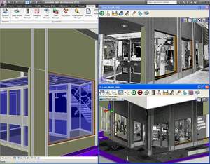
  • Direct Integration: Integrate laser data with Revit directly, without sub-sampling or converting to “polygon meshes.”
  • Laser Models: Display 3D BIM models using solid, high-definition
  • Laser Models for direct remodeling or to create new designs.
  • Laser Image Projection: Project 3D BIM models into Laser Images of individual 3D laser scans for real-time validation or design reviews.
  • Measurement: Measure points, distances and mechanical or plumbing pipe information between the 3D BIM model, Laser Images and Laser Models.
  • Clashing: Clash laser data and 3D BIM models to verify remodeling accuracy or identify interferences with new designs.
  • Demolition: Group Laser Models that are parts of the facility being demolished and highlight or hide them for planning or design analysis.
  • Multi-user Database: Share measurements across the team via a multi- user database to ensure consistent information and easier interactions.
  • State Manager: Store and recall laser data (Laser Models, Laser
  • Images and views) to focus on areas or interest and more quickly resume work.

By using QuantaCAD to put reality in Revit, BIM remodeling time can be reduced while ensuring accuracy, design time can be decreased by accessing complete and clear Laser Models and Laser Images that represent existing conditions, and rework from design clashes can be eliminated by correcting clashes between the Laser Models and the new design.

If you are interested in finding out more about accessing laser data in Revit using QuantaCAD or would like a demonstration, visitwww.quantapoint.com/qp/contact or e-mail info@quantapoint.com.

About Quantapoint

Quantapoint uses patented laser scanning technology to create a high-resolution Digitized Facility(TM) of Laser Models(TM) (not “point clouds”) and Laser Images(TM) that can be accessed directlywithin various CAD packages or integrated with facility and asset information. By putting critical facility as-built information at our client’s fingertips, Quantapoint has helped them reduce costs, optimize schedules, increase quality and improve safety. For more information on our technology and services, please visit www.quantapoint.com, e-mail info@quantapoint.com or call +1-412-653-0100.

Image Available: http://www2.marketwire.com/mw/frame_mw?attachid=1101374

Add to Digg Bookmark with del.icio.us Add to Newsvine

For additional information, please contact:

James McGill
VP of Marketing
Quantapoint, Inc.
Telephone: 412-653-0100, x-200
E-mail: jmcgill@quantapoint.com

REVIEW: Leica Geosystems ScanStation C10 and Cyclone 7

On Sepember 1, 2009, Leica Geosystems and Point of Beginning Magazine hosted a webinar titled The Business of Laser Scanning — hype or competitive advantage? Presenters Michael Harvey and Frank Hahnel along with Kristi Grahl discussed using laser scanning technology to:

  • Submit more competitive bids — and win more jobs — for both high-end projects and routine surveys.
  • Meet the requirements of customers who increasingly incorporate HDS into their project specifications.
  • Lower your labor costs and increase profit margins on every job.
  • Increase customer satisfaction with more accurate and detailed surveying reports.

During the webinar, the presenters also announced the availability of Leica’s new ScanStation C10 self-contained time-of-flight 3D laser scanner along with Cyclone 7, Cloudworx for SmartPlant3D and Forensic Map.

Some of the benefits of the new ScanStation C10:

  • No cables
  • On-board data storage
  • USB Interface for data transfer
  • Uses Internal Lithium-Ion TPS Total Station Batteries
    • Hot-swappable
    • 3.5 – 4 hours per battery
    • 4 come with scanner
  • GPS antenna and prism mount attachements
  • Automatically switches between oscillate/spin mirror mode to improve speed
  • Can still be used with a laptop
  • 180-degree sweep – scans both sides
  • Higher resolution capability
  • Integrated color touch-screen
  • Light-weight – 28.6 lbs (scanner),
  • More Portable – 62 lbs (scanner in case)
  • Dual High-resolution camera/video with auto exposure and auto focus
    • Faster target acquisition by point and shoot using the on-board color touch screen
    • Acquire full dome images in 4-7 minutes
  • Man Machine Interface (MMI)
    • Similar to Leica TPS Total Stations
  • Shorter Start-up time
  • Low scan power
  • Withstands moisture better than ScanStation 2

Cyclone 7 Features:

  • Updated Traverse Editor
  • Improved meshing capabilities
    • Leica acquired 3Dreshaper – new meshing functionality
    • Meshing of tunnels
  • Point Cloud engine is real-time indexed – faster viewing performance

View this webcast on-demand. The archive will be available for one year from the live broadcast.

Request your FREE on-site demo — Want to see the new ScanStation c10 in action? Reserve your spot at www.leica-geosystems.us/c10.

REVIEW: ClearEdge3D EdgeWise – Automatic Point Cloud to 3D Model Conversion

Company: ClearEdge3D
Software: EdgeWise™
Website: www.clearedge3d.com

Quick Pitch: Automatically extract vector planar surfaces from just about any type of point cloud data.

Overview:
Having used just about every piece of software on the market related to processing and extracting vector data from point clouds, I am always looking for the next best thing. The hardware side of laser scanning has come a long way in a very short period of time. However, the software side has not improved at the same blistering pace. When the availability of ClearEdge3D’s EdgeWise™ software was announced back in June and webinars were hosted to demonstrate the abilities of the software, I was anxious to get my hands on a copy of EdgeWise™ to test it out for myself. While a little reluctant to offer demo licenses in the beginning, ClearEdge3D quickly began to realize that skeptics like myself were not willing to spend $7,000.00 on a piece of software that we have not had a chance to try out for ourselves, especially in this economy. They quickly began to recognize the needs of the market and responded accordingly by providing time-based pre-release beta trials to highly interested parties.

Installation:
The pre-release software I received (v. 1.0.2b) was easy to install, although there was an issue with the hardware lock driver on my Vista 64-bit laptop. This was quickly resolved by downloading the correct driver from the SafeNet website (Note: the updated drivers will be included on future distrobutions).

First Impression:
Right out of the box (figuratively speaking, as the software was downloaded from their website) I was very impressed with the overall look and feel of the software. ClearEdge3D was obviously interested in making their software easy to use and graphically pleasing to the eye because they certainly did accomplish that. The UI is based on the latest Microsoft Office-type menu structure which made it very easy to jump right in.

Ease of Use:
ClearEdge3D insisted on a 1-hour web-based training session and, while not necessarily needed due to the exceptional design and layout of the software itself, it did prove to be very benefical and probably saved me a bit of time learning by trial and error. With exception to a few terminology questions, I found the software’s left-to-right workflow very easy to use. Every step of the conversion process was very well thought out and the routines made a lot of sense.

REVIEW:: ClearEdge3D EdgeWise™ – High Definition CAD Models Automatically From Point Clouds

EdgeWiseCompany: ClearEdge3D
Software:
EdgeWise™
Website: www.clearedge3d.com

Quick Pitch: Automatically extract vector planar surfaces from point cloud data.

Overview:
Having used just about every piece of software on the market related to processing and extracting vector information from point cloud data, I am always looking for the next best thing that will make my life and my team’s life easier. We have seen the hardware side of laser scanning come a long way in a very short period of time; however, the software side has not improved at the same blistering pace.

When the availability of ClearEdge3D’s EdgeWise™ software was announced here back in June and webinars were hosted to demonstrate the abilities of the software, I was anxious to get my hands on a copy of it to test it out for myself. While a little reluctant to offer demo licenses in the beginning, ClearEdge3D quickly began to realize that skeptics like myself were not willing to spend $5,000.00 on a piece of software that we have not had a chance to try out for ourselves, especially in this economy. They quickly began to recognize the needs of the market and responded accordingly by providing time-based pre-release beta trials to highly interested parties.

Installation:
The pre-release software I received (v. 1.0.2b) was easy to install, although there was an issue with the hardware lock driver on my Vista 64-bit laptop. This was quickly resolved by downloading the correct driver from the SafeNet website (Note: the updated drivers will be included on future distributions).

First Impression:
Right out of the box (figuratively speaking, as the software was downloaded from their website) I was very impressed with the overall look and feel of the software. ClearEdge3D was obviously interested in making their software easy to use and graphically pleasing-to-the-eye because they certainly did accomplish that. The UI is based on the latest Microsoft Office-type menu structure which made it very easy to jump right in.

EdgeWise-CaptureEase of Use:
ClearEdge3D insisted that I attend a 1-hour web-based training session and, while not necessarily needed due to the exceptional design and layout of the software itself, it did prove to be very beneficial and probably saved me the headache of learning by trial and error. With exception to a few terminology questions, I found the software’s left-to-right workflow very easy to use. Every step of the software’s conversion process was very well thought out and the routines made sense, technically speaking.

Technical Aspects:
While the software was primarily designed for the Architectural/BIM workflow, I have to admit that I was a little skeptical about the benefits of automatic conversion vs. the time needed to export the point cloud data to a format EdgeWise™ would accept (non-gridded PTX was the format of choice). Having been in the terrestrial laser scanning business over nine years, I know that point cloud data can be very cumbersome to deal with, especially when having to export to different formats. However, I was pleasantly surprised with EdgeWise’s ability to quickly import the various PTX files that I wanted to test.

NOTE: For those Cyclone users out there, EdgeWise™  is an automated “region grow patch, extend patch to all” batch routine. It really does a great job of quickly identifying planar surfaces and extending the edges to meet adjacent planes. The data import and processing time was a lot faster than I expected, but I did drastically reduce the number of points (to about 1 million).

Workflow:

  1. Export point cloud data (individual scans) to format accepted by EdgeWise™ (see FAQ on company’s website for more information on formats)
  2. Import individual scans into EdgeWise™
  3. Follow a few simple steps to identify the location of the scanner
  4. Extract ground surface (TIN)
  5. Let the software work its magic – it really is as simple as that!


Summary:
If you have a significant amount of basic models that need to be created from point cloud data, EdgeWise™ would likely be a good investment. Keep an eye on this product, because they are definitely on to something and, with a little direction from qualified users, they are on track to change our typical workflow.

Leica Geosystems Announces the Release of Leica CloudWorx™ 1.0 for SmartPlant 3D

Leica Geosystems Announces the Release of Leica CloudWorx™ 1.0 for SmartPlant 3D

(Heerbrugg, 21 July 2009) Leica Geosystems announces the immediate availability of Leica CloudWorx™ 1.0 for SmartPlant 3D. This powerful and easy-to-learn point cloud solution is designed for Intergraph SmartPlant 3D users who want to take full advantage of accurate, laser scan as-built data directly in SmartPlant 3D.

Leica CloudWorx™ 1.0 for SmartPlant 3D is the latest addition to the Leica CloudWorx suite of products that enable professionals to use rich, as-built point cloud data directly in their native desktop design and visualization platform. SmartPlant 3D is Intergraph’s next generation plant design platform.

Key features and capabilities of Leica CloudWorx™ 1.0 for SmartPlant 3D
– Measure – using SmartPlant 3D’s own measuring tools
– Automated clash checking – using SmartPlant 3D’s built-in clash management and reporting tools
– Pipe centerline routing tools and exact tie-point location tools – for finding face of flange at pipe center; supports creation of intelligent as-built models directly in SmartPlant 3D, using catalog components and objects
– Leica Geosystems’ unique Key Plan features – for visual fast navigation within point cloud project data
– Leica Geosystems’ unique TruSpace viewer – delivers improved comprehension of point cloud data and ease of driving exact viewpoints in the CAD system
– Easy point cloud management – by Scan, “Limit Box”, “Cutplane slices and sections”, and “Hide Region”
– Supports a variety of laser scanners – including native data formats from Leica Geosystems scanners, the industry’s most popular scanners
– CloudWorx toolbars – access CloudWorx operations easily, conveniently, and fast;
visualize a new design concept directly in context with reality

High Accuracy Plus High Performance
Leica CloudWorx for SmartPlant 3D is based on Leica Geosystems’ long proven database-centric Cyclone™ point cloud foundation, which allows users to simultaneously benefit from state-of-the-art spatial accuracy and high performance point cloud management.

Powerful Point Cloud Management & Measurement in SmartPlant 3D
Leica CloudWorx for SmartPlant 3D provides several ways to quickly, efficiently, and effectively manage vast amounts of point cloud data. User named and defined “Cutplane Slices and Half-Space Sections” and/or “Limit Boxes” provide a quick and easy way to navigate point cloud data. These selections can be recalled as needed on demand. The Key Plan and TruSpace viewpoint management tools provide unsurpassed ease-of-use and improved visual comprehension. Measurements are taken using familiar SmartPlant 3D measuring tools.

Automated Point Cloud Clash Detection and Reporting Using SmartPlant 3D
Clash detecting against point clouds with Leica CloudWorx is performed using SmartPlant 3D’s own automated clashing and reporting tools. Users can automatically detect clashes between modeled objects and point clouds, based on a user’s own defined tolerance settings. All interfering points within a user-defined region are visually highlighted and itemized.

Supports Multiple Scanner Formats
Leica CloudWorx for SmartPlant 3D lets Intergraph’s users take advantage of spatial scan data from any laser scanner via industry-standard ASCII-based data formats. In addition, Leica CloudWorx for SmartPlant 3D directly accepts, without any data format conversion, compact native data formats from the industry’s most popular scanners. These include all models of Leica Geosystems High-Definition Surveying™ (HDS™) time-of-flight and phase-based laser scanners, and selected scanners from other vendors. This capability to accept native formats from the industry’s most popular scanners provides users with even higher overall system efficiencies and simpler workflows.

Pricing & Availability
Leica CloudWorx 1.0 for SmartPlant 3D is immediately available from Leica Geosystems. Pricing information is available through appropriate Leica Geosystems representatives and dealers worldwide.

Leica Geosystems – when it has to be right
With close to 200 years of pioneering solutions to measure the world, Leica Geosystems products and services are trusted by professionals worldwide to help them capture, analyze, and present spatial information. Leica Geosystems is best known for its broad array of products that capture accurately, model quickly, analyze easily, and visualize and present spatial information.

Those who use Leica Geosystems products every day trust them for their dependability, the value they deliver, and the superior customer support. Based in Heerbrugg, Switzerland, Leica Geosystems is a global company with tens of thousands of customers supported by more than 3’500 employees in 28 countries and hundreds of partners located in more than 120 countries around the world. Leica Geosystems is part of the Hexagon Group, Sweden.

For further information please contact:

Leica Geosystems AG
Bill Wallace
Sr. Product Manager, Software

Tel (direct) 1-925-790-2356
Tel (central) 1-925-790-2300
Fax 1-925-790-2309
E-mail: bill.wallace@leica-geosystems.com

www.leica-geosystems.com/hds


Autodesk Announces Availability of Autodesk Navisworks 2010 with Point Cloud Operability

SAN RAFAEL, Calif., June 23 /PRNewswire-FirstCall/ — WHAT:

Autodesk Navisworks 2010: – Autodesk, Inc. , a world leader in 2D and 3D design and engineering software, announced that it is shipping new releases of Autodesk Navisworks 2010 software for managing, simulating, and reviewing design and engineering projects in 3D. Autodesk Navisworks 2010 provides new capabilities that manage multi-disciplinary plant design and engineering workflows and enhance coordination across distributed teams. New plant-relevant features include:

Clash grouping and detection – Autodesk Navisworks combines precise faultfinding with hard, soft, clearance, and time-based clash management. Engineers can more quickly review and cross-check geometry created by most 3D authoring software; maintain a complete record of all clashes found throughout a project; check time and space coordination; and resolve site and workflow issues at the planning stage.

Multi-format support – Compatible with most major 3D design and laser scan formats, Autodesk Navisworks can combine 3D data from multiple formats, regardless of file size, into a comprehensive, dynamic information model, which can be shared with all stakeholders. Autodesk is committed to providing multi-format support and will work to provide compatibility with new file formats as they emerge.

Collaboration – Autodesk Navisworks enables design teams across engineering disciplines to view, annotate, expand, revise, and analyze one comprehensive information model for informed, timely decision-making. All project review files saved in Navisworks format are compressed, more secure, and streamable, and can be easily viewed with the free* Navisworks viewer.

In addition to these engineering design capabilities, Autodesk Navisworks 2010 will be compatible with the forthcoming AutoCAD Plant 3D product.

  CUSTOMER REFERENCES:

  Unison Engineering & Consultants GmbH, Germany

“Navisworks’ point- and line-based clash detection allow us to coordinate laser-scanned as-built environments with virtual models,” said Leandros Zeppos, managing director at Unison Engineering & Consultants, an independent engineering company, providing a wide spectrum of engineering services for the plant industry. “The easy visualization of 3D point-cloud models with the integration of 3D CAD models provides a powerful design review solution for any project. Engineering solutions can be easily analyzed against existing, accurate on-site data.”

Lenzing Technik GmbH, Austria

“Navisworks has simplified our job immensely,” said Gerd Bergner, an engineer at Lenzing Technik, a global industrial partner specializing in Engineering and Contracting, Mechanical Engineering and Industrial Services, and Automation and Mechatronics. “The planning and design processes needed for steel-erection and plant-engineering work can now be combined into a single model. As a result, the plant project can be reviewed, and those involved now have a much better feeling for the installation they are creating.”

MORE INFORMATION:

For more information and a free* trial version of Autodesk Navisworks software, please visit http://www.autodesk.com/navisworks-plant.

*These products are subject to the terms and conditions of the end-user license agreement that accompanies each software product.

  CONTACT:
  Brett Smith
  brett.smith@autodesk.com
  (415) 547-2405

  Carey Godbee
  cgodbee@b3communications.com
  (760) 758-4406

  About Autodesk

Autodesk, Inc., is a world leader in 2D and 3D design and engineering software for the manufacturing, building and engineering, and media and entertainment markets. Since its introduction of AutoCAD software in 1982, Autodesk has developed the broadest portfolio of state-of-the-art Digital Prototyping solutions to help customers experience their ideas before they are real. Fortune 1000 companies rely on Autodesk for the tools to visualize, simulate, and analyze real-world performance early in the design process to save time and money, enhance quality, and foster innovation. For additional information about Autodesk, visit http://www.autodesk.com/.

Occasionally, Autodesk makes statements regarding planned or future development efforts for our existing or new products and services. These statements are not intended to be a promise or guarantee of future delivery of products, services, or features but merely reflect our current plans, which may change. The Company assumes no obligation to update these forward-looking statements to reflect any change in circumstances, after the statements are made.

Autodesk, AutoCAD and Navisworks are registered trademarks or trademarks of Autodesk, Inc., and/or its subsidiaries and/or affiliates in the USA and/or other countries. All other brand names, product names or trademarks belong to their respective holders. Autodesk reserves the right to alter product offerings and specifications at any time without notice, and is not responsible for typographical or graphical errors that may appear in this document.

Pointools Launches new Software: Pointools Edit

Written by: Pointools

The challenges of managing and working with large point cloud datasets efficiently and maximising their value has been the primary concern of point cloud software specialists Pointools who have recently announced the availability of the eagerly-awaited flagship product Pointools Edit.

Key Features
Pointools Edit builds on the features of the successful Pointools View Pro, adding a new set of tools and enhancements in key areas without compromising performance. Like View Pro, Edit is also based on the Vortex point cloud engine designed to deliver productivity with huge datasets. Pointools say their focus with Edit has been to provide a post-registration toolkit that prepares point cloud data for production of deliverables reducing the overall project production time. Edit has been tested rigorously in production environments to ensure it delivers, even for most demanding projects.

Layers
Point layers are one of Edit’s most unique and powerful features. For example cleaning noise from an interior scan is made easier by moving the walls into another layer, allowing the user to focus on the interior. Once complete, the walls can be moved back to the original layer. Layers can also be locked effectively acting as a mask. Once a user grasps this methodology, editing that may have in the past taken many hours can now take minutes to complete with fewer commands needed.

Editing
In addition to the standard rectangle and polygon selection tools, Edit provides a 3d brush tool for easy selection of objects in complex environments. Selections are fast and utilise multiple CPU cores if available. When working with huge point datasets, density can be reduced for faster operation and on export the editing will automatically be reapplied to every point.

RGB Retouching
RGB values in point clouds can be re-touched using a colour matching and 3d brush with layers for masking and precise control. Photo editing filters such as brightness/contrast, hue/saturation can also be applied and the results saved to the point cloud file. Where the presentation of the point cloud data is important, this can fix mis-mapped obstructions or sky areas on scan data as well as scanner ‘circles’ not covered by photography.

For more information visit www.pointools.com

About Pointools
Pointools Ltd are a specialist software company producing a range of products for working with point cloud data. A UK company founded in 2003, Pointools products have thousands of users across the world. Pointools software accepts data from almost any laser scanner with many manufacturer’s native formats supported. Pointools Edit follows on from Pointools View Pro, Pointools Model for AutoCAD and Pointools4Rhino. Pointools products can be purchased from a network of resellers worldwide.

Too-cool technologies: Game Engine-quality Point Clouds and Digital Holography

By Lieca N. Hohner, Chief Editor SparLLC

Our industry never comes short in the innovation department. HKS Inc., headquartered in Dallas, Texas, proves this—it’s turned “regular” point clouds into game-engine quality. Here’s the story. And then read on for some amazing display solutions.
HKS, Inc.’s Pat Carmichael, manager of the Advanced Technology Group, began investigating point cloud scans as a way to achieve high-quality as-built information for the company’s architectural geometry applications used for schematic design (most often Revit). The team realized many benefits using laser scan data, including the ability to obtain data not manually possible, draw while acquiring field data, gain highly accurate data comparable to total station data, and to collect immense amounts of data in rapid time. Point clouds are the bread and butter of rapid model acquisition, Carmichael said in his presentation at SPAR 2009.
HKS scan data captured from subcontractors’ scanners are used in HKS’ home-grown product called BIMMIT, an evolving spin-off product from their real-time game-engine product ARCHengine that has been in development for more than 10 years and that which enhances Revit models. BIMMIT is usually coupled with HKS’ proprietary ARCHengine for real-time display of the resulting 3D BIMMIT/Revit models, which can be between 8 million to 30 million polygons depending on their use on a laptop or desktop.
To illustrate the awesomeness of this melding, consider the W hotel in Dallas. The final model of the pre-constructed hotel designed by HKS was used to show city officials how the hotel’s sight lines would affect the downtown skyline so valued by the city. It was also used to sell out the associated condos prior to construction, as developers could take prospective buyers virtually up to their windows to show the views from their units. This same concept was used for the Ritz-Carlton twin towers in downtown Dallas; the presentation helped to pre-sell approximately 85% of the Phase One units in about six months—even in this down market, Carmichael said.
HKS used aerial lidar from the city to set elevations, some of which are photographically textured. HKS also flies with a RED ONE digital camera, which shoots in 4K resolution, whereby they extract high-resolution textures rapidly for application with the aerial lidar geometry. Most of the building models come out of Revit.
With these incredible design tools, HKS also performed a design review on the seating in the new American Airlines sports arena. HKS showed staff, team owners and other investors how seats would articulate and rise for a hockey or basketball arena and specifically how they would affect viewlines. On the new Dallas Cowboys Stadium in Arlington, Texas, HKS took the collected field scan data, structural data and drawing data—and all site views from all 89,000 seats, scoreboards, etc., into ARCHengine. To check the models during construction, HKS used a total station to get information from point to point. In the desktop models of the ARCHengine tools, everything is georeferenced with lat/long/elev, which gives the team dimensional data.
“It’s a serious design tool,” Carmichael said. “It’s a serious communication tool to the clients/users/vendors, all the other suppliers, and a bunch of other people participating in the design process.”
Carmichael says the next version of ARCHengine version 3 will tie individual objects to a reporting structure, in line with 4D business strategies that tie in time, space calculations and scheduling. He said HKS Advanced Technology Group is also working with Intel on the high-end multi-processors to be able to react more quickly to a cluster of cores for simulations.
Those involved in sports stadium, government, military or GSA work will be interested in HKS’ Advanced Technology Group solutions.
To see an interactive map of the seats in the new Dallas Stadium with panoramic images generated from ARCHengine, click tohttp://www.dallascowboys.com/tickets/newstadiumInteractiveMaps.cfm

Digital Imaging, Holographic Style

Zebra Imaging, Inc., provider of holographic display technologies, has taken visualization of LiDAR and laser scan data sets to a new level. Users in the geospatial, AEC, automotive, medical, oil & gas, military and other arenas can view a topographical data set in full parallax, full color and without any glasses or goggles. “Seeing LiDAR and laser scanned data volumetrically expands its utility and value,” said Michael Klug, Zebra’s CTO, at this year’s SPAR 2009. Government and commercial uses seem endless.
Zebra’s solution graduates a physical display to digital holography by reconstructing a 3D image in space using film-based displays and illumination. The 12-year-old company founded by graduates of the Massachusetts Institute of Technology’s Media Lab has cut its teeth by aiding the military and law enforcement with displays that assist planning and after-action efforts, situational awareness and training.
It’s pretty cool stuff—a far, FAR cry from the hologram stickers I collected as a little girl. Klug describes the process as being more like burning data to a disc rather than a printing process. From a pair of GeoTiffs (one being a DEM, the other a geotextured map), Zebra’s proprietary Imager burns the pattern into photopolymer film with intersecting laser beams and produces an A1-size (594 × 841 mm) monochrome hologram that can be produced in CAD, GIS, medical imaging, oil & gas, etc., formats in 1-millimeter hogel size—about a pixel. Process time is about three hours. An average A1-size monochrome (green) hologram costs about $2,500. Full color and replication is available, and Klug says high-speed development will be available by Q4. Klug claims Zebra’s solution is similar or lower cost compared to other market alternatives today, and that it is more transportable and usable with full solid parallax 3D.
Zebra has produced more than 6,000 LiDAR-based holographic displays for military use in Iraq and Afghanistan since 2006. The 2×2 ½-foot maps provide warfighters with a common communication tool to get a common operating picture of an area of interest without language or cultural obstacles. Klug said they’re easily transportable and durable and, later, shreddable.
Focus on AEC Market
In the last two years, the company has developed a new product line for the AEC realm. Attention focuses on geospatial context and all phases of design, BIM documentation, and communications and marketing.
Currently, Zebra is defining a styles guide and a CAD tool API plug-in-based interface available from a drop-down menu in Revit, 3DS Max and Google Sketchup (at first, then others). Klug says the creation of a wizard is a bit complicated for Zebra since they render with in-house tools to manage 64,000 to a quarter-million views of a scene within two hours. So, they’ve created a render-quality selection where the user can select a point cloud, a simple-shaded rendition of a data set, a textured data set or a photo-real selection (which customizes the job). Orders are returned in A-frame and horizontal format (each of which delivers different results) and include a lighting component.
The Creation of Dynamic Displays
In 2004, Zebra was sponsored by DARPA to create a program for dynamic 3D displays for interactive graphic-intensive applications.  The dynamic displays would be easy to view, have 360-degree visibility, be electronically updated in real-time, be modular and scalable to 6×6 feet, and offer horizontal, vertical and inclined orientations. To date, they’ve established a 1-meter diagonal prototype modular display of 8-inch square tiles with an image volume that occupies about 1 foot of space. It directly plugs into OpenGL-based applications and updates at 10 Hz. Pilot production and beta phase of this display is expected next year. Klug said any rendering feature a user can see on a 2D screen can be produced in the hologram, including translucency, transparency, reflection, etc.

Uses for these displays include, but don’t appear to be limited to, spatial, project and industrial process planning, land development, event security logistics, emergency management, heritage preservation, forensics presentation and construction progress monitoring.