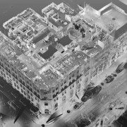
From Tiltan’s website: TLiD is Tiltan’s innovative solution for fast, automated creation of 3D maps and GIS information from LiDAR point clouds.
TLiD Main Features:
– Automatic extraction of DTM (bare earth) and DSM
– Automatic features extraction (houses, trees, power lines)
– Automatic full scene 3D reconstruction
– LAS or free ASCII txt input
– LAS, SHP, DTM and other output file formats
– Multiple input/output coordinate systems
– Integrated with a 3D Viewer
TLiD Advantages:
– Fast parallel processing for cost reduction
– No limitation on input file size
– Standalone product
– Special Applications
– Trees counting – height and size
– Power line mapping and clearance
– Line of sight
– Other applications – available on request
https://scanable.com/wp-content/uploads/2010/04/Tiltan-e1271777040959.jpg165716Travis Reinkehttps://scanable.com/wp-content/uploads/2025/01/SCANable_logo_emblemSimple-180x180.pngTravis Reinke2010-04-20 08:24:232010-04-20 08:24:23Tiltan TLiD Transform LiDAR Point Clouds to 3D Models in One Keystroke
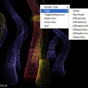
Creating animations of large point cloud datasets generated from terrestrial laser scanners and LiDAR has been an issue for a number of years. While it has been possible using tools such as Leica Geosystems Cyclone or Pointools, just to name a couple, it is still a very cumbersome task. It is exciting to see the CGI industry beginning to adopt the use of this data and developing applications that make it easier to visualize.
Over the last few years, a brand new technology has emerged for creating CGI effects that has already made a big impact on feature film production. It is called point-based rendering, and this powerful technique makes creating global illumination effects for feature film far more practical and efficient than before. In fact, this year the Academy of Motion Picture Art and Sciences awarded the creators of this innovation, Per Christensen, Michael Bunnell and Christophe Hery, with a Scientific and Engineering Academy award.
In this great article written by Nils O Sandys at CGSociety, we will look into the development of this important new technology, how point-based rendering works, and what this all means to the future of feature film production as we know it. Read the full article here.
SCANable is evaluating this promising new software and will follow-up with an indepth review in the coming days. In the meantime, please feel free to check it out for yourself and leave your input here.
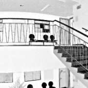
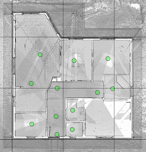
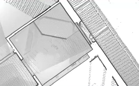
Automatic analysis and interpretation of laser scanning data
Floor plans, views and sectional views are created at the push of a button.
Program offers an intuitive user interface (no training required).
For the first time, results can be processed in almost all CAD programs.
Visual representations allow a direct use and will dramatically reduce time needed for analysis and modeling.
Point-Cab is the first application that automatically creates―at the push of a button―floor plans and sectional views. The goal of the development team has been to create an extremely user-friendly interface design.
The program creates a visual representation of laser scanning data. The result has much more expressiveness and validity than individual points of point clouds. Images and representations of sections are a prerequisite for an easy modeling in CAD programs.
The program supports most of the common CAD programs and construction tools through standard interfaces. You may use the results in ArchiCAD, Google SketchUp, Revit and other tools.
Find out for yourself why this revolutionary program can make such a difference for you.Click here to download the Point-Cab trial version. The trial version can be used for 15 hours. Time is consumed when you use the application. Feel free to also download our laser scanning data examples. Please find all data examples here.
Here you can download the processed layout results of the full version of Point-Cab.
https://scanable.com/wp-content/uploads/2010/04/Laserscan1.png193300Travis Reinkehttps://scanable.com/wp-content/uploads/2025/01/SCANable_logo_emblemSimple-180x180.pngTravis Reinke2010-04-13 14:55:122010-04-13 14:55:12Create Floor Plans Automatically from 3D Point Clouds [Point-Cab]
SAN RAFAEL, Calif.–(BUSINESS WIRE)–Autodesk, Inc. (NASDAQ:ADSK) announced the availability of the 2011 AutoCAD software products, including AutoCAD 2011 software, a leading 2D and 3D design and documentation platform, and AutoCAD LT 2011 software for professional 2D drafting and detailing. The latest releases of AutoCAD deliver powerful new features — such as new tools for surface modeling and transparency for objects and layers — that can help designers explore their ideas and maximize productivity. The 2011 AutoCAD products are Microsoft Windows 7 certified and are compatible with and supported on Windows 7 Home Premium, Professional, Enterprise, and Ultimate as well as Windows Vista and Windows XP operating systems.
“We have also implemented many of the top features requested by Autodesk User Group International (AUGI) members and focused on providing new tools that are quick to learn but can have a big impact in everyday work.”
“In the 2011 releases we have continued to invest in increasing drafting productivity and have added a strong set of new 3D modeling features for conceptual design that will help millions of AutoCAD users worldwide take their designs further,” said Guri Stark, vice president, AutoCAD and Platform Products. “We have also implemented many of the top features requested by Autodesk User Group International (AUGI) members and focused on providing new tools that are quick to learn but can have a big impact in everyday work.”
AutoCAD 2011 gives designers more advanced conceptual design tools as well as increased flexibility and control when designing in 3D:
New surface modeling tools enable users to easily create smooth surfaces and surface transitions, while associativity maintains relationships between all of the objects.
Point cloud support for up to two billion points enables users to quickly visualize scanned objects directly within the modeling workspace.
Inferred constraints enable designers to define constraints as they draw.
Hatch command enhancements bring improved drafting efficiency, while new gradient hatch patterns enable users to add more colors and shading to drawings.
TimeSaver tools, previously available only to customers on Autodesk Subscription, are now available to all AutoCAD users.
AutoCAD LT 2011 builds on its reputation for productivity with new commands that make everyday tasks more efficient. In addition to the hatch command enhancements and TimeSaver Tools found in AutoCAD 2011, AutoCAD LT 2011 adds new tools that give users additional options for controlling the appearance of drawings:
Transparency for objects and layers provides new options for managing the appearance of drawings and communicating design intent.
New multifunctional polyline grips make editing polylines significantly faster and easier.
The ability to create or select similar objects based on the properties of existing objects helps users save time when drawing and editing geometry.
Industry Solutions for the AutoCAD 2011 Products
The updated AutoCAD 2011 software portfolio includes the following industry-specific applications built on the AutoCAD platform:
AutoCAD Architecture 2011 software for efficient architectural drafting and documentation has new geometric and dimensional constraints and renovation tools to help accelerate design.
AutoCAD Electrical 2011software helps electrical controls designers to quickly create control system designs and easily access extensive catalog information for large electrical controls projects.
AutoCAD Mechanical 2011 software’s streamlined design environment gives users vastly improved access to power dimensioning functionality, which automatically aligns part dimensions with the rest of the drawing properties, without ever opening a dialog box.
AutoCAD MEP 2011software provides greater drafting productivity for mechanical, electrical and plumbing (MEP) designers and drafters and has new features for creating and storing AutoCAD block names, sloped piping and parallel conduit routing.
Autodesk, Inc., is a world leader in 2D and 3D design, engineering and entertainment software for the manufacturing, building and construction, and media and entertainment markets. Since its introduction of AutoCAD software in 1982, Autodesk continues to develop the broadest portfolio of state-of-the-art software to help customers experience their ideas digitally before they are built. Fortune 100 companies — as well as the last 15 Academy Award winners for Best Visual Effects — use Autodesk software tools to design, visualize and simulate their ideas to save time and money, enhance quality and foster innovation for competitive advantage. For additional information about Autodesk, visit www.autodesk.com.
Autodesk, AutoCAD and AutoCAD LT are registered trademarks or trademarks of Autodesk, Inc., and/or its subsidiaries and/or affiliates in the USA and/or other countries. Academy Award is a registered trademark of the Academy of Motion Picture Arts and Sciences. All other brand names, product names or trademarks belong to their respective holders. Autodesk reserves the right to alter product and services offerings, and specifications and pricing at any time without notice, and is not responsible for typographical or graphical errors that may appear in this document.
https://scanable.com/wp-content/uploads/2010/03/210kingscan1.jpg319700Travis Reinkehttps://scanable.com/wp-content/uploads/2025/01/SCANable_logo_emblemSimple-180x180.pngTravis Reinke2010-03-30 17:05:132010-03-30 17:05:13Autodesk Expands Power of AutoCAD 2011 with New Point Cloud Support
Presented by: Executives from Spar Point research, Pointools, and Bentley
Summary:On October 14, 2009, Bentley announced that it had signed a “Continuous Technology Transfer Agreement” to incorporate Pointools’ Vortex Engine in the Bentley Technology Platform to enable reuse of 3D laser scanned data. This webinar will include three different perspectives on this agreement. To see the future of 3D data integration and platform interoperability you have to attend this webinar.
What you can learn:
An overview by Spar Point Research of the impact that laser scanning technology is having on the design, construction, and management of industrial plant, BIM, and civil/transportation infrastructure assets
The importance of integrating this technology into the daily workflows of infrastructure professionals and the value users will realize from this integration
A brief demonstration by Pointools of the Vortex engine functionality including an explanation on why the Pointools’ technology is so fast and so capable of handling billions of point clouds at one time
Watch this eSeminar by chapter:
These videos open directly into your media player.
PITTSBURGH, PA — (Marketwire) — 10/29/09 — Quantapoint (http://www.quantapoint.com) — recent recipient of a General Services Administration (GSA) laser scanning IDIQ contract — announced the integration of Quantapoint 3D laser scan data with Autodesk® Revit using QuantaCAD(TM). Laser data may be accessed directly within Revit as photo-realistic Laser Images(TM) of individual 3D laser scans and high-definition Laser Models(TM) of integrated laser data, not fuzzy “point clouds” whose sparse measurements make them difficult to use and understand.
“One of the challenges of Building Information Modeling (BIM) has been creating 3D BIM models that accurately represent existing buildings,” said Eric Hoffman, Founder of Quantapoint. “By integrating Laser Models and Laser Images with Revit, Quantapoint can more quickly create 3D BIM models and validate their accuracy. Additionally, new 3D BIM designs can be viewed and clashed with the laser data to ensure that they will fit into the existing facility, thus eliminating rework.”
QuantaCAD provides a number of useful capabilities to Revit users to enable them to create and validate 3D BIM models, visualize proposed modifications for design and constructability reviews, and identify and correct potential interferences. Some of the capabilities include:
Direct Integration: Integrate laser data with Revit directly, without sub-sampling or converting to “polygon meshes.”
Laser Models: Display 3D BIM models using solid, high-definition
Laser Models for direct remodeling or to create new designs.
Laser Image Projection: Project 3D BIM models into Laser Images of individual 3D laser scans for real-time validation or design reviews.
Measurement: Measure points, distances and mechanical or plumbing pipe information between the 3D BIM model, Laser Images and Laser Models.
Clashing: Clash laser data and 3D BIM models to verify remodeling accuracy or identify interferences with new designs.
Demolition: Group Laser Models that are parts of the facility being demolished and highlight or hide them for planning or design analysis.
Multi-user Database: Share measurements across the team via a multi- user database to ensure consistent information and easier interactions.
State Manager: Store and recall laser data (Laser Models, Laser
Images and views) to focus on areas or interest and more quickly resume work.
By using QuantaCAD to put reality in Revit, BIM remodeling time can be reduced while ensuring accuracy, design time can be decreased by accessing complete and clear Laser Models and Laser Images that represent existing conditions, and rework from design clashes can be eliminated by correcting clashes between the Laser Models and the new design.
James McGill
VP of Marketing
Quantapoint, Inc.
Telephone: 412-653-0100, x-200
E-mail: jmcgill@quantapoint.com
https://scanable.com/wp-content/uploads/2010/03/QuantaPoint.jpg58300Travis Reinkehttps://scanable.com/wp-content/uploads/2025/01/SCANable_logo_emblemSimple-180x180.pngTravis Reinke2009-10-29 14:54:512009-10-29 14:54:51Quantapoint Announces Integration of 3D Laser Scan Data With Autodesk(R) Revit(R)
Ottawa, Canada, Wednesday, October 28, 2009 – Ambercore is pleased to announce its point cloud technology has been incorporated into the release of AutoCAD® Civil 3D® 2010 and AutoCAD® Map 3D 2010, part of Autodesk’s Subscription Advantage Packs. These releases are the first products from Autodesk that incorporate Ambercore’s technology which provides valuable new functionality for importing and visualizing large point cloud data sets.
Point clouds are extremely large data sets with millions of points, and are typically created through the use of laser scanning, high-definition surveying, or LiDAR (Light Detection and Ranging). They provide accurate representations of existing conditions of terrain surfaces, roadways, bridges, and the interior or exterior of features of buildings.
Some common uses of LiDAR data in AutoCAD® Civil 3D® and AutoCAD® Map 3D include using the point cloud data to create DEMs and contour data, digitizing as-built features for design projects, visualizing power lines and surrounding vegetation for right-of-way management, and developing an understanding of the site context in site surveys.
The Ambercore point cloud technology within the AutoCAD® Civil 3D® 2010 and AutoCAD® Map 3D 2010 products enables customers to read, store, index, and quickly retrieve the extremely large point cloud data sets associated with laser scanning and LiDAR. As a result, customers are able to visualize and analyze data in 3D and better build high-precision 3D models.
“The point cloud technology from Ambercore allows Autodesk AEC customers to easily incorporate extremely large and highly accurate LiDAR data into their infrastructure design and management processes,” said Charlie Crocker, Infrastructure Product Line Manager, Autodesk AEC (Architecture, Engineering, and Construction) solutions. “The incorporation of this technology into AutoCAD Civil 3D and AutoCAD Map 3D software means that our customers will be able to better plan, design, and manage infrastructure projects.”
“We are very excited about the first release of our technology within Autodesk’s AutoCAD® Civil 3D® and Map 3D products,” said Ted Reeler, Director, Projects & Technology at Ambercore. “We are confident that this new functionality for point clouds will be a significant asset to their customers, and we look forward to our ongoing collaboration with Autodesk.”
About Ambercore
Ambercore is the 4D Company. We make innovative mobile LiDAR technology, we provide LiDAR data collection services, and integrate and extract knowledge from 4D data. Ambercore’s 4D-iQ provides enterprise-scale software and service solutions for Energy, Mining and natural resource sectors. With its powerful spatial modeling and simulation software, 4D-iQ helps clients make important business decisions by collecting, integrating and analyzing spatial information in 2D, 3D and in 4D (over time).
TITAN® is a revolutionary technology that produces high accuracy survey and mapping products for corridor and infrastructure projects across a number of vertical markets. Travelling at highway speeds – or on rail or vessel – the system uses state-of-the-art LiDAR, imaging and positioning technology to provide feature rich 3-dimensional data, from which intelligent information is extracted and delivered to clients. TITAN® has been deployed on projects throughout the world since 2003.
Ambercore’s Terrapoint Division has provided LiDAR and other digital mapping services for a diverse clientele in over forty countries for the past twenty years. Terrapoint’s primary focus is to find solutions that fit client needs, and to continue a reputation for meeting and exceeding client demands in the delivery of digital elevation and image data. Service and product offerings include complete airborne LiDAR, and digital imaging for engineering, survey and mapping applications. Terrapoint is considered a leader in aerial LiDAR services, and owns one of the largest fleets of sensors in the world. Best of breed solutions comprised of software, hardware and services have been deployed internationally with tier-one clients. Ambercore is headquartered in Ottawa, Canada with offices in Houston, Calgary, South Africa and Europe.
https://scanable.com/wp-content/uploads/2025/01/SCANable_logo_emblemSimple-180x180.png00Travis Reinkehttps://scanable.com/wp-content/uploads/2025/01/SCANable_logo_emblemSimple-180x180.pngTravis Reinke2009-10-29 13:58:222009-10-29 13:58:22Autodesk Releases Subscription Advantage Packs with Ambercore Point Cloud Technology
On Sepember 1, 2009, Leica Geosystems and Point of Beginning Magazine hosted a webinar titled The Business of Laser Scanning — hype or competitive advantage? Presenters Michael Harvey and Frank Hahnel along with Kristi Grahl discussed using laser scanning technology to:
Submit more competitive bids — and win more jobs — for both high-end projects and routine surveys.
Meet the requirements of customers who increasingly incorporate HDS into their project specifications.
Lower your labor costs and increase profit margins on every job.
Increase customer satisfaction with more accurate and detailed surveying reports.
During the webinar, the presenters also announced the availability of Leica’s new ScanStation C10 self-contained time-of-flight 3D laser scanner along with Cyclone 7, Cloudworx for SmartPlant3D and Forensic Map.
Quick Pitch: Automatically extract vector planar surfaces from just about any type of point cloud data.
Overview: Having used just about every piece of software on the market related to processing and extracting vector data from point clouds, I am always looking for the next best thing. The hardware side of laser scanning has come a long way in a very short period of time. However, the software side has not improved at the same blistering pace. When the availability of ClearEdge3D’s EdgeWise™ software was announced back in June and webinars were hosted to demonstrate the abilities of the software, I was anxious to get my hands on a copy of EdgeWise™ to test it out for myself. While a little reluctant to offer demo licenses in the beginning, ClearEdge3D quickly began to realize that skeptics like myself were not willing to spend $7,000.00 on a piece of software that we have not had a chance to try out for ourselves, especially in this economy. They quickly began to recognize the needs of the market and responded accordingly by providing time-based pre-release beta trials to highly interested parties.
Installation:
The pre-release software I received (v. 1.0.2b) was easy to install, although there was an issue with the hardware lock driver on my Vista 64-bit laptop. This was quickly resolved by downloading the correct driver from the SafeNet website (Note: the updated drivers will be included on future distrobutions).
First Impression:
Right out of the box (figuratively speaking, as the software was downloaded from their website) I was very impressed with the overall look and feel of the software. ClearEdge3D was obviously interested in making their software easy to use and graphically pleasing to the eye because they certainly did accomplish that. The UI is based on the latest Microsoft Office-type menu structure which made it very easy to jump right in.
Ease of Use:
ClearEdge3D insisted on a 1-hour web-based training session and, while not necessarily needed due to the exceptional design and layout of the software itself, it did prove to be very benefical and probably saved me a bit of time learning by trial and error. With exception to a few terminology questions, I found the software’s left-to-right workflow very easy to use. Every step of the conversion process was very well thought out and the routines made a lot of sense.
https://scanable.com/wp-content/uploads/2025/01/SCANable_logo_emblemSimple-180x180.png00Travis Reinkehttps://scanable.com/wp-content/uploads/2025/01/SCANable_logo_emblemSimple-180x180.pngTravis Reinke2009-08-04 21:29:562009-08-04 21:29:56REVIEW: ClearEdge3D EdgeWise – Automatic Point Cloud to 3D Model Conversion
Quick Pitch: Automatically extract vector planar surfaces from point cloud data.
Overview: Having used just about every piece of software on the market related to processing and extracting vector information from point cloud data, I am always looking for the next best thing that will make my life and my team’s life easier. We have seen the hardware side of laser scanning come a long way in a very short period of time; however, the software side has not improved at the same blistering pace.
When the availability of ClearEdge3D’s EdgeWise™ software was announced here back in June and webinars were hosted to demonstrate the abilities of the software, I was anxious to get my hands on a copy of it to test it out for myself. While a little reluctant to offer demo licenses in the beginning, ClearEdge3D quickly began to realize that skeptics like myself were not willing to spend $5,000.00 on a piece of software that we have not had a chance to try out for ourselves, especially in this economy. They quickly began to recognize the needs of the market and responded accordingly by providing time-based pre-release beta trials to highly interested parties.
Installation:
The pre-release software I received (v. 1.0.2b) was easy to install, although there was an issue with the hardware lock driver on my Vista 64-bit laptop. This was quickly resolved by downloading the correct driver from the SafeNet website (Note: the updated drivers will be included on future distributions).
First Impression:
Right out of the box (figuratively speaking, as the software was downloaded from their website) I was very impressed with the overall look and feel of the software. ClearEdge3D was obviously interested in making their software easy to use and graphically pleasing-to-the-eye because they certainly did accomplish that. The UI is based on the latest Microsoft Office-type menu structure which made it very easy to jump right in.
Ease of Use:
ClearEdge3D insisted that I attend a 1-hour web-based training session and, while not necessarily needed due to the exceptional design and layout of the software itself, it did prove to be very beneficial and probably saved me the headache of learning by trial and error. With exception to a few terminology questions, I found the software’s left-to-right workflow very easy to use. Every step of the software’s conversion process was very well thought out and the routines made sense, technically speaking.
Technical Aspects: While the software was primarily designed for the Architectural/BIM workflow, I have to admit that I was a little skeptical about the benefits of automatic conversion vs. the time needed to export the point cloud data to a format EdgeWise™ would accept (non-gridded PTX was the format of choice). Having been in the terrestrial laser scanning business over nine years, I know that point cloud data can be very cumbersome to deal with, especially when having to export to different formats. However, I was pleasantly surprised with EdgeWise’s ability to quickly import the various PTX files that I wanted to test.
NOTE: For those Cyclone users out there, EdgeWise™ is an automated “region grow patch, extend patch to all” batch routine. It really does a great job of quickly identifying planar surfaces and extending the edges to meet adjacent planes. The data import and processing time was a lot faster than I expected, but I did drastically reduce the number of points (to about 1 million).
Workflow:
Export point cloud data (individual scans) to format accepted by EdgeWise™ (see FAQ on company’s website for more information on formats)
Import individual scans into EdgeWise™
Follow a few simple steps to identify the location of the scanner
Extract ground surface (TIN)
Let the software work its magic – it really is as simple as that!
Summary:
If you have a significant amount of basic models that need to be created from point cloud data, EdgeWise™ would likely be a good investment. Keep an eye on this product, because they are definitely on to something and, with a little direction from qualified users, they are on track to change our typical workflow.
https://scanable.com/wp-content/uploads/2025/01/SCANable_logo_emblemSimple-180x180.png00Travis Reinkehttps://scanable.com/wp-content/uploads/2025/01/SCANable_logo_emblemSimple-180x180.pngTravis Reinke2009-08-04 15:05:172009-08-04 15:05:17REVIEW:: ClearEdge3D EdgeWise™ – High Definition CAD Models Automatically From Point Clouds


 Presented by: Executives from Spar Point research, Pointools, and Bentley

 PITTSBURGH, PA — (Marketwire) — 10/29/09 — Quantapoint (
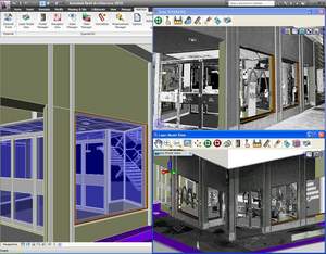 Direct Integration: Integrate laser data with Revit directly, without sub-sampling or converting to “polygon meshes.”
 Some of the benefits of the new
  Company: ClearEdge3D
 Ease of Use: