SAN RAFAEL, Calif., June 23 /PRNewswire-FirstCall/ — WHAT:
Autodesk Navisworks 2010: – Autodesk, Inc. , a world leader in 2D and 3D design and engineering software, announced that it is shipping new releases of Autodesk Navisworks 2010 software for managing, simulating, and reviewing design and engineering projects in 3D. Autodesk Navisworks 2010 provides new capabilities that manage multi-disciplinary plant design and engineering workflows and enhance coordination across distributed teams. New plant-relevant features include:
Clash grouping and detection – Autodesk Navisworks combines precise faultfinding with hard, soft, clearance, and time-based clash management. Engineers can more quickly review and cross-check geometry created by most 3D authoring software; maintain a complete record of all clashes found throughout a project; check time and space coordination; and resolve site and workflow issues at the planning stage.
Multi-format support – Compatible with most major 3D design and laser scan formats, Autodesk Navisworks can combine 3D data from multiple formats, regardless of file size, into a comprehensive, dynamic information model, which can be shared with all stakeholders. Autodesk is committed to providing multi-format support and will work to provide compatibility with new file formats as they emerge.
Collaboration – Autodesk Navisworks enables design teams across engineering disciplines to view, annotate, expand, revise, and analyze one comprehensive information model for informed, timely decision-making. All project review files saved in Navisworks format are compressed, more secure, and streamable, and can be easily viewed with the free* Navisworks viewer.
In addition to these engineering design capabilities, Autodesk Navisworks 2010 will be compatible with the forthcoming AutoCAD Plant 3D product.
  CUSTOMER REFERENCES:

  Unison Engineering & Consultants GmbH, Germany
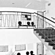
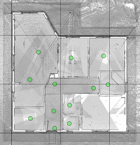
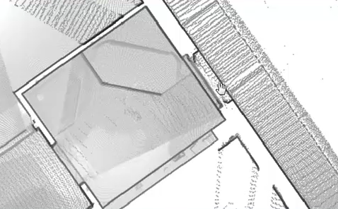
“Navisworks’ point- and line-based clash detection allow us to coordinate laser-scanned as-built environments with virtual models,” said Leandros Zeppos, managing director at Unison Engineering & Consultants, an independent engineering company, providing a wide spectrum of engineering services for the plant industry. “The easy visualization of 3D point-cloud models with the integration of 3D CAD models provides a powerful design review solution for any project. Engineering solutions can be easily analyzed against existing, accurate on-site data.”
Lenzing Technik GmbH, Austria
“Navisworks has simplified our job immensely,” said Gerd Bergner, an engineer at Lenzing Technik, a global industrial partner specializing in Engineering and Contracting, Mechanical Engineering and Industrial Services, and Automation and Mechatronics. “The planning and design processes needed for steel-erection and plant-engineering work can now be combined into a single model. As a result, the plant project can be reviewed, and those involved now have a much better feeling for the installation they are creating.”
MORE INFORMATION:
For more information and a free* trial version of Autodesk Navisworks software, please visit http://www.autodesk.com/navisworks-plant.
*These products are subject to the terms and conditions of the end-user license agreement that accompanies each software product.
  CONTACT:
  Brett Smith
  brett.smith@autodesk.com
  (415) 547-2405

  Carey Godbee
  cgodbee@b3communications.com
  (760) 758-4406

  About Autodesk
Autodesk, Inc., is a world leader in 2D and 3D design and engineering software for the manufacturing, building and engineering, and media and entertainment markets. Since its introduction of AutoCAD software in 1982, Autodesk has developed the broadest portfolio of state-of-the-art Digital Prototyping solutions to help customers experience their ideas before they are real. Fortune 1000 companies rely on Autodesk for the tools to visualize, simulate, and analyze real-world performance early in the design process to save time and money, enhance quality, and foster innovation. For additional information about Autodesk, visit http://www.autodesk.com/.
Occasionally, Autodesk makes statements regarding planned or future development efforts for our existing or new products and services. These statements are not intended to be a promise or guarantee of future delivery of products, services, or features but merely reflect our current plans, which may change. The Company assumes no obligation to update these forward-looking statements to reflect any change in circumstances, after the statements are made.
Autodesk, AutoCAD and Navisworks are registered trademarks or trademarks of Autodesk, Inc., and/or its subsidiaries and/or affiliates in the USA and/or other countries. All other brand names, product names or trademarks belong to their respective holders. Autodesk reserves the right to alter product offerings and specifications at any time without notice, and is not responsible for typographical or graphical errors that may appear in this document.


 Presented by: Executives from Spar Point research, Pointools, and Bentley

 PITTSBURGH, PA — (Marketwire) — 10/29/09 — Quantapoint (
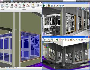 Direct Integration: Integrate laser data with Revit directly, without sub-sampling or converting to “polygon meshes.”
 Company: ClearEdge3D
 Ease of Use: